1. Weight drive:
This clock is driven by a weight suspended on a string, which is wound around a pulley. I have aimed for a weight between 250g and 350g. This is not so heavy that the gearing and axles show excessive wear in long term use and not so light that the clock is close to stopping. The wear occurs particularly in the higher torque areas of the clock during rewind, such as the lower differential gearbox.
2. Auto-rewind:
You can see the autowind working on this YouTube Link to R3. Most mechanical clocks are driven by a lowering weight which needs raising up every day or so by hand by winding a gear or pulling a chain, then the clock needs restarting. It became clear that with this clock I would struggle to achieve a useful runtime of more than a few hours between rewinds, so the average busy person could not be expected to keep it running. I didn’t want to build a motor driven clock and I didn’t want to rewind it every few hours by hand. Also I was keen to avoid using excessively heavy weights to drive the clock. So I needed an automated rewind method built into the gearing that didn’t let the clock stop during rewinding. The solution uses a differential gearbox, which could automatically rewind and raise the weight back up while still driving the clock forwards. A switching mechanism turns on the motor every half hour or so when the weight drops to a certain level.

So, in this arrangement,
B = ½ (A + C)
Normally, the motor isn’t running and C is locked, so the weight just drives the escapement. B is constrained to move very slowly, say, 0.1 rpm and A drives at 0.2rpm. However, when the rewind motor is switched on, C turns relatively quickly, say, 10rpm. In this condition:
0.1 = ½ (A + 10)
So A = -9.8rpm – ie the drive rewinds, and crucially, the torque on B remains positive.
The need for auto-rewinding in LEGO clocks is driven by the following factors:
- Materials: being plastic, the lego axles have a relatively high axle diameter to gear diameter compared with conventional clocks, and so the friction to torque ratio is also relatively high. Without using excessive weight (as this would lead to excessive wear) this limits the fundamental gearing ratio between the drive pulley and the escapement wheel itself (1:62.5).
- Weight travel: having small children in our house, I needed the weight to stay always out of reach, which limited me to a short weight travel. Before we were blessed with this particular design constraint I had the weight travel some 1.5 metres all the way to the floor and used a trip switch on the floor to activate the motor.

So I have ended up with a decent compromise: a clock which winds itself up every half hour and doesn’t try to push the limits of strain and wear on the Lego.
3. Escapement:
This clock uses a basic Deadbeat escapement style: a rocker on top of the pendulum which is driven by angled teeth on a special gear wheel, invented by Richard Towneley around 1675: http://en.wikipedia.org/wiki/Deadbeat_escapement#Deadbeat_escapement.
Lego does not lend itself easily to escapement and most solutions I have seen are not very compact. The conventional technical Lego gear has teeth which are too steep to drive radial movement and the impulses fail. For ages I used a metal Meccano wheel with shallower teeth and pins stuck into drinking straws as the rocker, then later found the handy 8 toothed propeller which has the sloped gears.

Some great examples of escapements are to be found on utube by searching “lego escapement”. Achieving a low friction pendulum fulcrum to suspend the pendulum from was equally difficult. An axle passing through a technical plate would be too high friction. Eventually the best system I could find was to use a small rocking 8 toothed gear located on a rack. This works quite well until the gear wears and makes more than 1point of contact with the rack.
4. Time-adjust:
The time-keeping using this escapement is not marvellous, and can wander perhaps a few minutes each day. The period can be adjusted by changing the length of the pendulum according to the formula for pendulum Simple Harmonic Motion (SHM) (L/g)0.5. As the escapement is far from isochronous (ie the condition whereby frequency is independent of driving force or pendulum amplitude), the clock’s speed will vary with small changes in gearing friction. This could be improved by increasing the pendulum’s mass to reduce the ‘driven’ component of the swing, but I have been reluctant to do this to minimise wear and friction on the suspending fulcrum and to minimise necessary driving mass (currently <0.5kg target). So, in fact another way of fine tuning the clock speed is to adjust the main driving weight. I have heard that Big Ben used to be adjusted by the engineer placing old penny pieces on the weight. If someone can come up with a better pendulum fulcrum I am sure the timekeeping could be improved.
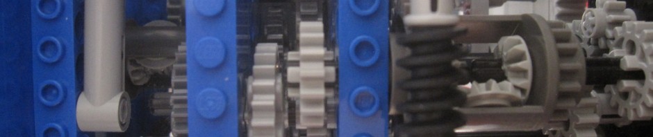
A second differential gearbox locked against a worm gear is used to allow the user to adjust the hands. This is visible in the header image at the top of this page.